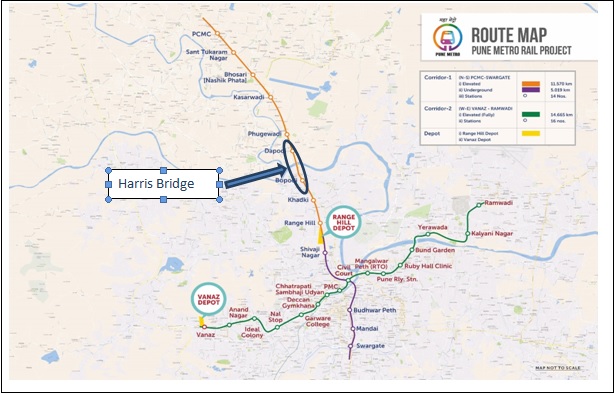
Launching of Structural Steel Girders for Harris Bridge by Incremental Launching
method for Elevated Viaduct of Reach-1 in Corridor-1 (PCMC-Swargate) for Pune
Metro Rail Project.
The alignment of the Pune Metro Rail Project on Reach-1 of Corridor-1, on the elevated
viaduct, is crossing river Pawana near Dapodi. This river crossing is through Harris Bridge
consisting of 11 no’s of spans (HB1 to HB12), out of which 7 no’s of spans (HB1 to HB4 &
HB9 to HB12) is located on the approach of the river on either side. And, 4 no’s of spans
(HB4 to HB8) are located in the river portion.
All 11 spans are designed with structural steel composite girders. The span-wise span lengths
of the Harris Bridge from HB1 to HB12 is 25.1m, 43.5m, 45.75m, 28.42m, 43.59m, 42.98 m,
43.08m, 43.5m, 40.0m, 40.0m, and 34.09m respectively. Each span consists of two sets of
two steel girders of 2.422m depth kept side by side and both the girders of each set are
connected by cross bracing. The weight of one girder varies from 21.5 MT to 47.5 MT and
the weight of all 4 girders of one span varies from 85 MT to 220 MT.
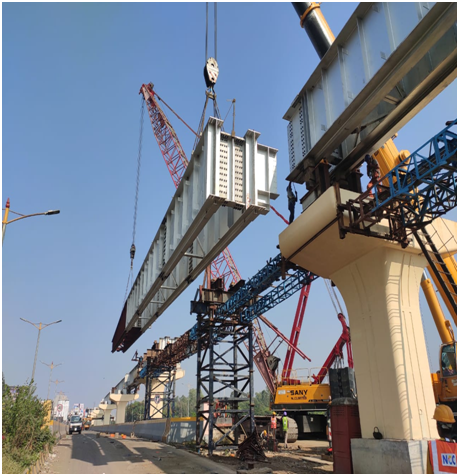
Erection of 7 structural steel girders on either side of the river is done by Tandem Lifting
Method in which the steel girders are first assembled at ground level and then lifted and
placed in position with the help of two road cranes of required capacity which are handling
each set of steel girder from either end. However, a girder erection of central 4 spans, piers of
which are located on the river bed, was not possible by Tandem Lifting Method due to
constraints of placing heavy capacity road cranes on the deck of existing road bridges, as the
existing road bridges are old structures. Hence, Incremental Launching Method was adopted
for 4 central spans (HB4 to HB8) within the river bed.
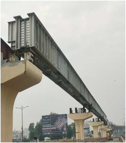
Incremental Launching Method (HB 4 to 8)
The temporary supports are erected within approach spans for supporting the steel girders
temporarily before they are launched by incremental method into their final locations.
Hillman & guide rollers are fixed on each temporary supports for the movement of the steel
girders. The capacity of the Hillman roller is 100 MT and 02 nos of Hillman rollers are
provided on one temporary support. Total 22nos of Hillman rollers were provided. Side
rollers are also provided to guide the pulling direction of girders to ensure that girders move
in the desired direction. One set of two plate girders of the first two spans is first assembled
on erected temporary supports.
The splicing of these girders is done to make a longitudinal continuous member facilitate
their movement during the pulling process. After connecting wire rope arrangement, the
whole assembly of plate girders is pulled with a winch machine for about 43m. The capacity
of pulling the winch is 20MT. While the girders are being pulled from the PCMC end, the
restraining winch of equal capacity 20MT is also provided on the PMC end to avoid any
accidental slippage of girders during the pulling or pulling getting out of control. After
completion of the first set launching, the next set of two plate girders of the last two spans is
assembled on erected temporary supports. These two girders shall be attached to the already
pushed girder back with splicing. Now the whole assembly of four girders shall be pulled
with the winch machine. Once a set of two girders are pulled and placed in their final
designated position under the track and the same procedure is adopted for the other side pair
of two girders also. After the completion of pulling off all four girders, the girder shall be
lowered on bearings for final alignment and further construction activities.
Written by :
– Gautam Birhade, IRSE, Executive Director/Viaduct/R1&R2
– K. C Sukumar, CRE/Viaduct/R1&R2